Does the process designer know the piping designer is suggesting a change to the physical layout by rerouting the piping to provide clearance from a pump with a larger footprint than initially expected?.Examples such as these must be checked to ensure consistency and resolve changes: Bridging this gap, and making all diagrams consistent, must be validated during engineering, procurement and construction (EPC).


In most cases, the documents are not produced by the same team, and they are typically created on incompatible types of software tools.īoth activities must happen simultaneously to keep the schedule on time, yet it is very difficult to ensure these two teams talk to each other routinely, stay current with changes on either side and continually update all documents. Problems occur when there are inconsistencies among these documents, often stemming from the origins of the different renderings. Both must deliver the required level of detail for their purposes and be consistent with each other.

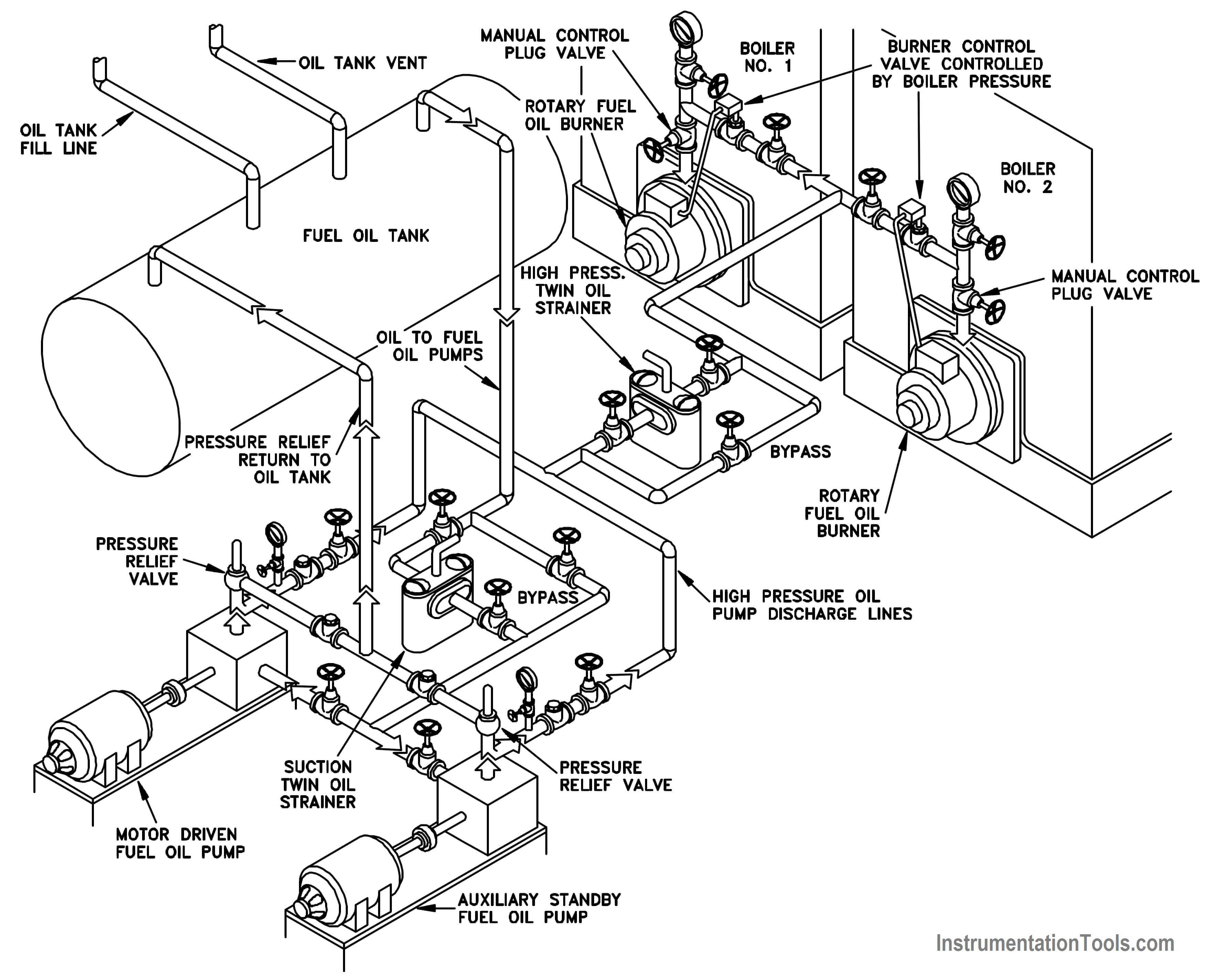
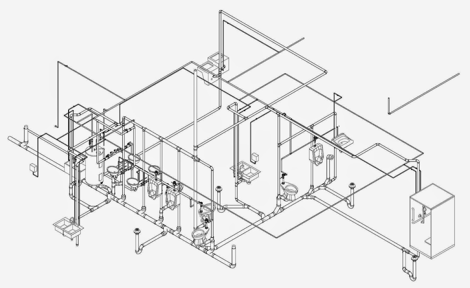
These provide x-, y-, and z-axes able to indicate what piping is vertical and horizontal. 3-D techniques can also concentrate on just the piping in conjunction with the full 3-D plant model and isometric piping diagrams. The 3-D model with isometric piping diagrams, provides more analysis of physical layout. The P&ID (Figure 1) is assumed to have extensive detail related to the process design. The piping design team creates the 3-D models with supporting isometric drawings: Here is how we must build the equipment to implement the requirements laid out in the P&ID.The process design team creates the P&ID: Here is the piping we need to make the process work.Why? Because the two formats are designed to convey different types of information, and different teams use each format as needed: On the other hand, an engineer trying to configure piping and mechanical elements will concentrate on the 3-D models and associated isometric drawings. In many situations, an engineer trying to perform serious process analysis will spend more time with a traditional process and instrumentation diagram (P&ID). Some readers may respond that 3-D plant modeling has been available for years now, and has indeed become very sophisticated, and it contributes to construction of a plant. Suitable for analysis or just visualization? For example, when a process engineer or plant manager is looking at the plans for new production unit or plant, 3-D visualization is a major improvement as compared to traditional methods.

Viewers can analyze and understand spatial relationships much more easily than by looking at a collection of simple photos. 3-D models are effective because they help all parties concerned get a far deeper understanding of a project than traditional 2-D methods.


 0 kommentar(er)
